UV printing injection molding parting line / BUYER GUIDE
UV Printing Around Gates, Ejector Marks and Parting Lines: A Plastic Housing DFM Guide
A B2B buyer guide to planning direct uv print boundaries around gates, ejector marks and parting lines on moulded plastic housings: scope the product, validate the real blank, control production risk, and prepare for shipment inspection.

The direct answer for procurement teams
The practical decision is whether the visible decorative area avoids moulding features and local surface changes that can compromise the approved appearance or fixture reference. A material name by itself is not enough. Parts with the same nominal material can differ in mould release residue, surface texture, protective film, colour, local flatness, and tolerance. Ask the factory to test a production-equivalent part and to document what the approved sample is intended to prove.
Where this requirement appears in real products
Phone-case shells, electronic enclosures, speaker fronts, appliance covers and injection-moulded promotional housings is a useful example because the surface is expected to look deliberate while remaining practical to assemble, handle, protect, and inspect. In a typical feasibility review, the team maps the visible face, identifies ports, camera cut-outs, vents, buttons, clips, screw holes, or mounting zones, and agrees which areas must remain free of ink.
The factory should then confirm the printable panel and head clearance on the actual part. This is installation preparation: the physical component must locate in a stable way before an artwork file can become a repeatable batch. A drawing is helpful; a real blank is better.
Material and surface questions to resolve first
Moulded hard-plastic parts can contain gates, ejector marks, weld lines and parting-line features that are small in CAD but obvious under side light or close inspection. The Plastics Industry Association's mould-finish guide illustrates why surface-finish terminology needs an agreed physical reference. Surface preparation must be decided from the observed part rather than assumed from a sales specification. Cleanliness, coatings, static attraction and surface-energy differences can change how an ink layer appears and performs. A controlled factory test can compare an untreated area with any proposed preparation route, but it should not be represented as a universal result for every supplier or production lot.
ISO 20457:2026 provides a plastics-specific reference for dimensional and geometric acceptance conditions; use it alongside the actual part drawing and approved appearance sample.
| Buyer input | Why it matters | What to approve |
|---|---|---|
| Production-equivalent blank | Confirms the usable area and surface condition | A labelled sample or retained reference part |
| Final artwork and layer file | Defines colour, white, gloss and keep-out zones | The exact revision used for the first-off |
| Handling and assembly brief | Reveals contact, abrasion and packing exposure | A realistic review condition |
| Quantity and packing plan | Determines fixture and batch-control needs | The agreed inspection and pack-out approach |
Factory testing: what a useful sample proves
A useful sample does not merely show that an image can be printed. It should use the intended part, the agreed artwork boundary, any white or clear layer, and a repeatable locating reference. Reviewers can then assess position, edge quality, visible colour direction, finish, functional exclusions and the relevant handling condition.
Review the physical blank under the intended viewing angle, mark all moulding features and cosmetic exclusions, then make a first-off in the selected fixture. Keep the approved image boundary and reference part available for production and shipment inspection. The factory should record the part orientation, artwork revision and fixture reference used for the approved sample. If those inputs change later, treat the change as a new approval question rather than assuming the original result carries over.
Production risk: avoid the common wrong assumptions
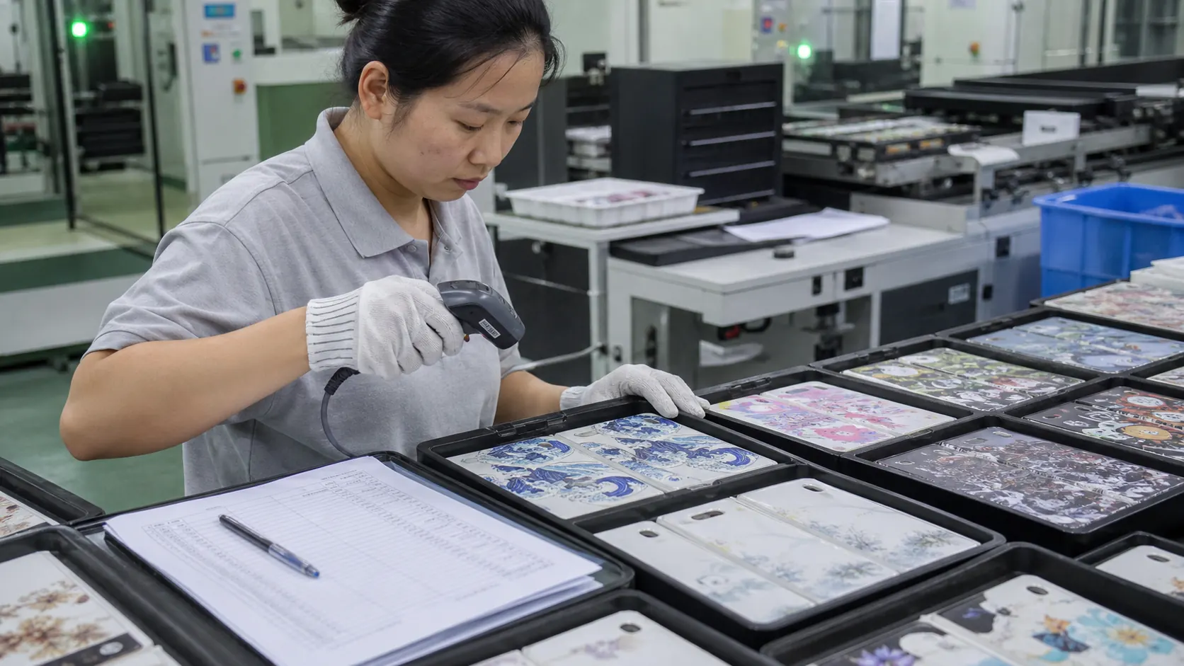
The risk is treating the cosmetic face as a perfect flat rectangle. A print can cross a local sink, step or edge and still register correctly in a fixture while looking uneven in use. Moving the graphics or defining a keep-out zone before sampling is usually more controllable than trying to hide a physical feature afterwards. The most reliable response is to make the risk observable before batch release: retain the approved sample, agree a check point, and specify what must be protected in packing. This is more useful than using broad statements such as "durable" or "works on plastic" without a product-specific definition.
Artwork boundaries are also manufacturing boundaries
For flat panels and shells, the image boundary must account for dimensional tolerance, raised features, edge roll-off, functional openings, and any region that will be masked, bonded, clipped or touched during assembly. An artwork file can include named keep-out layers so the commercial brief and shop-floor reference describe the same object.
Colour and finish need a viewing condition
If colour is important, provide the best available reference and state how it will be judged: under a neutral light source, at an agreed viewing distance, or against an approved printed sample. White ink can isolate a design from a dark or transparent base; Roland's white-base printing guidance illustrates why the substrate can influence apparent colour. Any white, gloss or matte effect should be approved on the final blank.
Mid-article CTA: Review Your Moulded Housing Print Boundary
Send product photos or a drawing, material details, a marked print area, artwork, quantity and target delivery date. We can help turn those customer requirements into a sample and inspection brief. For related planning, see our UV printable materials guide and fixture preparation guide.
A repeatable batch workflow
After approval, production should follow the same references used for the sample. That normally means confirming the product version, cleaning and loading method, fixture orientation, first-off check, in-process observation, segregation of nonconforming pieces, face protection, and carton arrangement. The objective is not to prescribe one machine setting for every part; it is to keep the validated variables stable long enough to deliver an inspectable batch.
- Confirm the approved blank, artwork revision and part orientation.
- Set the locating reference and compare several blanks for fit.
- Review the first-off against the approved sample before release.
- Check representative pieces for position, visible finish and functional keep-out zones.
- Protect printed faces and verify the agreed pack-out during shipment inspection.
Checklist for your enquiry and sample review
- Provide a part drawing plus physical blanks
- Mark gates, ejector marks, weld lines and cosmetic exclusions
- Set an artwork safe area from the real visible face
- Approve first-off placement under the agreed viewing condition
For an independent technical reference, Roland also explains reverse printing on acrylic and the use of white layers for transparent objects. The exact ink, primer, curing and evaluation method still need to match the selected equipment and the production part.
FAQ
Can we approve this from a digital render?
No. A render can confirm visual intent, but it cannot verify the real coating, local surface shape, print boundary, fixture location, visible finish or packing contact. Use it as an artwork reference and approve the physical sample separately.
Does one successful sample apply to every future order?
Only when the part, material or coating, artwork, finish, fixture and handling conditions remain controlled. If any of those variables change, the original sample should be reviewed before it becomes the acceptance reference again.
What should shipment inspection include?
Compare representative finished parts with the approved sample and written criteria. Check artwork revision, placement, visible defects, functional exclusions, face protection, carton configuration and any customer-specific packing requirement. Our pre-shipment inspection guide explains why the product and pack-out should be reviewed together.
Conclusion
planning direct UV print boundaries around gates, ejector marks and parting lines on moulded plastic housings is most reliable when the factory and buyer agree on the real component, the controlled print area, an approved sample and a simple inspection plan. That approach makes the workflow more transparent for sourcing teams and reduces the gap between a promising sample and a production-ready result.
Technical resources and next steps
Continue with our UV printable materials guide, supplier qualification checklist, and plastic-part QC checklist.
For independent technical background, review Epson's UV flatbed overview, Roland's smartphone-case handling guidance, and Mimaki's adhesion guidance. Validate every production decision on the actual blank and approved sample.